March 29, 2011

Resistor and Capacitor Applications


Resistor and capacitor are the key ingredients of many electronic circuit. Here are some reason why:


Power Supply Filter

A capacitor will smooth (filter) the pulsating voltage from a power supply into a steady direct current (DC).


Spike Remover

Digital logic circuit (which we'll find more about later in next article), can use lots of current momentarily when they switch from off to on or vice versa. This can cause very brief but substantial reductions in power applied to nearby circuits. These power spikes (or glitches, as they are sometimes called) can be eliminated by placing a small (0.1 uF) capacitor across the power leads of the logic circuit:


AC - DC Selective Filter

Often an electrical signal will be riding atop a steady DC signal. For example, the signal from a lightwave communication system may look like this when,


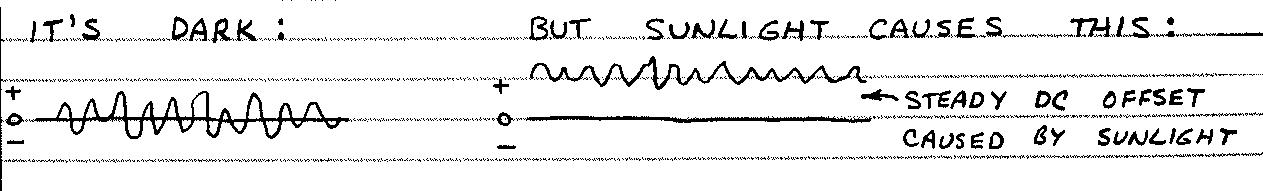
A capacitor will pass the fluctuating signal and completely block the steady DC level.


R-C Circuit

Two circuits that combine a resistor (R) and capacitor (C) are very important. They are the integrator and differentiator. Both these circuit are used to reshape an incoming stream of waves or pulses.

The product of an R and C in these circuits is called an RC Times Constant. For the circuits shown below, the RC time constant (in second) i9s at least ten times the interval between incoming cycles or pulses.

Integrator
Here's a basic RC integrator


If the input pulse are speeded up, the output waveform (often called a sawtooth) will not reach their full height (amplitude). It's easy to design an amplifier that ignores waves with less than a desired amplitude. Therefore, the integrator can function as a filter which passes anly signals below a certain frequency. 


Differentiator
Here's a basic RC differentiator

This circuit produces symmetrical output waves with sharp positive and negative peaks. It's used to make narrow pulse generators for television receivers and to trigger digital logic circuits.


More about R-C

You will often see reference to the RC time constant of a circuit. It's the time in seconds for a charging or discharging capacitor to go through 63.3% of the change in charge.


See also:

Resistor
Capacitor


Read more..

March 28, 2011

Capasitors


          There are many kinds of capacitors, but they all do the same thing: store electrons. The simplest capacitor is two conductor separated by an insulating material called dielectric. Like this:


The dielectric can be paper, plastic film, mica, glass, ceramic, air or vacuum. The plates can be aluminium discs, aluminium foil or a thin film of metal applied to opposite sides of a solid dielectric. The conductor-dielectric-conductor sandwich can be rolled into a cylinder or left flat.


How to Make a Capacitor?

You can make a capacitor from two sheet of aluminium foil and one sheet of waxed paper. Fold the paper around one foil sheet and stack the sheet like this:


Be sure the foil sheets don't thouch! Press the contacts of a 9-volt battery briefly to the expossed ends of the foil sheets. Then thouch the probes of a high-impedance multimeter to the foil sheet. The meter will indicate a small voltage for a few seconds. The voltage will then fall to zero.


Charging a Capacitor

The minus side of our homade capacitor is charged with electrons almost immediately. Since resistors limit current you can slow down the charging time by placing a resistor between the capacitor and the 9-volt battery:


Discharging a Capacitor

The electrons in a charged capacitor will gradually leak through yhe dielectric until both plate have an equal charge. The capacitor is then discharged. The capacitor can be discharged very quickly by connecting its plate together. Or it can be discharged more slowly by connecting a resistor across it:


Capacitor Symbols


WARNING!

Capacitor can store a chaege for a considerable time after the power to them has been switched off. This charge can be dangerous! A large electrolytic charged to only 5 or 10 volts can melt the tip of a screwdriver placed across its terminals! High voltage capacitors like those used in television sets and photoflash units can store a lethal charge! Never touch the leads of such a capacitor. At the very least the jolt can throw you across a room!


How Capacitor are Used?

Parallel Circuit
Often capacitors are connected in parallel like this. The total capacitance is the sum of the individual capacitance.


Series Circuit
Sometimes capacitors are connected in series like this. The total capacitance is the product of the two capacitances divided by their sum.


Three or more capacitors in series? Here's the formula:


Read more..

Resistors


           Resistors come in dozens of size and shapes but they all do the same thing: Limit current (or resist). More abou that later. First, let's see how a typical resistor is made:


"Carbon Composition" is just a vancy way of describing powdered carbon mixed with a glue-like binder. This kind of resistor is easy to make. And its resistance can be changed from one resistor to the next simply by changing the ratio of carbon particles to binder. More carbon gives less resistance.


Do-It-Your-Self Resistor

You can make a resistor by drawing a line with a soft lead pencil on the sheet of paper. Measure the resistance of the line or points along it by touching the probes of a multimeter to the line. Be sure to set the multimeter to its highest resistance scale. The resistance of a single line may be too high to measure. If so, draw over the line a dozen or so times. Here's what I measured:


Resistor Color Code

See those color code bands on the resistor pictorial? In real life they're kind of pretty. But they have a far more important purpose: they indicate the resistance of the resistor they decorate. Here's how:


Variable Resistor

Often it's necessary to change the resistance of a resistor. Variable resistor are called potentiometers. They are used to alter the volume of a radio, change the brightness of a lamp, adjust the calibration of a meter, etc. Trimmers are potentiometer equipped with a plastic thumbwheel or a slot for a srewdriver blade. They are designed for occasional adjustment.


Resistor Symbol


How Resistor are Used?

Series Circuit
Often resistor are connected in series like this. The total resistance is simply sum of the individual resistance.


Parallel Circuit
Resistor can also be connected in parallel like this. The total resistance is the product of the two resistance divided by their sum.


for three or more in parallel, go find your calculator because...


Voltage Division
SUPER IMPORTANT!


Vout is determined by ratio of R1 and R2. Here's the formula:


See also:

Capacitors
Resistor and Capacitor Applications


Read more..

March 27, 2011

Pulses, Waves, Signals and Noise


          Electronics is the study and application of electrons, their behaviour and their effects. The simplest application for electrons are straightforward AC and DC circuit in which a current is used to power lamps, electromagnets, motors, solenoids and similar devices. What takes electronics far beyond these basic applications is the ease with which streams of electrons can be controlled and manipulated.


This simple circuit is really useful bacause it can send information by converting a planned sequence of switch closures into flash of light.


Patterns of flashes or pulses like these can represent complex information like speech. Or speech can be transformed into proportional variation in the brightness of a lamp. Here's a simple way to send voise over a beam of reflected light:


Pulses

A pulse is a sudden, brief increase or decrease in a current flow. The ideal pulse would have an instantaneous rise and fall, but real pulses are not so ideal.


Waves

A wave is a periodic fluctuation in a current or voltage. Waves may have a single polarity (DC) or both positive or negative components (AC). There are many kinds of waves. Here are a few:


Signals

A signal is a periodic waveform that conveys information. The process that generates the waveform is called modulation. Signal can be AC, DC or AC riding on a DC level. Their enemy is . . .


Noise

All electronic devices and circuit generates small, random electrical currents. When these currents are unwanted, they're called noise. Noise can also enter electronics circuits by means of the electromagnetic waves generated by lightning, automobile ignition systems, electric motors and power lines. While noise may have a level of only a few millionths of a volt or ampere, it may easily abscure an equally low level signal.


Read more..

March 26, 2011

How Bipolar Transistor are Used?


          When the base of NPN transistor is grounded (0 volts), no current flows from the emitter to the collector (the transistor is "off"). If the base is forward-biased by at least 0.6 volt, a current will flow from the emitter to the collector (the transistor is "on"). When operated in only these two modes, the transistor function as a switch. If the base is forward-biased, the emitter-collector current will folow variations in amuch smaller base current. The transistor then function as an amplifier. This discussion applies to a transistor in which the emitter is the ground connection for both the input  and output and is called the common-emitter circuit. Some simplified common-emitter circuit are shown below. So you can see how they are used in real circuit.


A Bipolar Transistor Switch


Only two inputs are possible: ground (0 volt) and the positive battery (+V). Therefore the transistor is off or on. A typical base resistance is 5,000 to 10,000 ohms. (if the resistor is replaced by a wire, the lamp can be switched on or off from a considerable distance.)


A Bipolar Transistor DC Amplifier


The variable resistor forward biases the transistor and controls the input (base-emitter) current. The meter indicates the output (collector-emitter) current. The series resistor protects the meter from excessive current. In a working circuit, the variable resistor may be in series with a second component having a resistance that varies with temperature, light, moisture, etc. When the input signal changes rapidly, an AC amplifier such as the one below is used.


A Bipolar Transistor AC Amplifier

This is the simplest of several basic AC amplifiers. The input capacitor blocks any DC in the input signal.


The bias resistor is selected to give an output voltage of about half the battery voltage. The amplified signal "rides" on this steady output voltage and varies above and below it. (without the basis resistor, only the positive half of the input signal above 0.6 volt will be amplified. This will cause severe distortion.)


Read more..

Types of Diodes


Many different kinds of diodes are available. Here are some of the major types:


Small Signal

Small signal diodes are used to transform low current AC to DC, detect (demodulate) radio signals, multiply voltage, perform logic, absorb voltage spike, etc.


Power Rectifier

Functionally identical to small signal diodes, power rectifiers can handle much more current. They are installed in large metal package that soak up excess heat and transfer it to a metal heat sink. Use mainly in power supply.


Zener

The Zener diode is designed to have a specific reverse breakdown (conduction) voltage. This means Zener diode can function like a voltage sensitive switch. Zener diodes having breakdown voltages (Vz) of form about 2-volts to 200-volts are available.


Light Emitting

All diodes emit some electromagnetic radiation when forward biased. Diodes made from certain semiconductors (like Gallium Arsenide Phosphide) emit considerably more radiation than silicon diodes. They're called light-emitting diodes (LED's).


Photodiode

All diodes respond to some degree when illuminated by light. Diodes designed specifically to detect light are called photodiodes. They include a glass or plastic window through which the light enters. Often they have a large, exposed junction region. Silicon makes good photodiodes.


Read more..

The Transistor


          Transistor are semiconductor devices with three leads. A very small current or voltage at one lead can control a much larger current flowing through the other two leads. This means transistor can be used as amplifier and switches. There are two main families of transistor: Bipolar and Field-Effect.


Bipolar (Junction) Transistor

Add a second junction to a PN junction diode and you get a 3-layer silicon sandwich. The sandwich can be either NPN or PNP, either way, the middle layer acts like a faucet or gate that controls the current moving through the three layers.


Bipolar Transistor Symbol

Arrows point in direction of hole flow.


Bipolar Transistor Operation

The three layer of a bipolar transistor are the emitter, base and collector. The base is very thin and has fewer doping atoms than the emitter and collector. Therefore a very small emitter-base current will cause a much larger emitter-collector current to flow.

More About Bipolar Transistor Operation

Diodes and transistors share several key feature:

1. The base-emitter junction (or diode) will not conduct until the forward voltage exceeds 0.6-volt.

2. Too much current will cause a transistor to become hot and operate improperly. If a transistor is hot when touched, disconnect the power to it.


3. Too much current or voltage may damage or permanently destroy the semiconductor chip that forms a transistor. If the chip isn't harmed, its tiny connection wires may melt or separate from the chip. Never connect a transistor backwards!


to be continued..    Field-Effect Transistor


See also:

How Bipolar Transistor are Used?


Read more..

March 25, 2011

The Diode


          Both P-type and N-type silicon conduct electricity. The resistance of both type is determined by the proportion of holes or surplus electrons. Therefore both types can function as resistors. And they will conduct electricity in any direction.

By forming some P-type silicon in a chip of N-type silicon, electrons will flow through the silicon in only one direction. This is the principle of the diode. The P-N interface is called the PN juction.


How Diode Works

Here's a simplified explanation of how a diode conducts electricity in one direction (forward) while blocking the flow of current in the opposite direction (reverse).

Here the charge from the battery repels holes and electrons toward the junction. If the voltage exceeds 0.6-volts (silicon), then electrons will cross the junction and combine with holes. A current then flows.

Here the charge from the battery attracts holes and electrons away from the junction. Therefore, no current can flow.


A Typical Diode

Diode are commonly enclosed in small glass cylinders. A dark band marks the Cathode terminal. The opposite terminal is the Anode.


Diode Operation

We already know a diode is like an electronic one-way valve. It's important to understand some additional aspects of diode operation. Here some key ones:

1.   A diode will not conduct until the forward voltage reaches a certain threshold point. For silicon diode this voltage is about 0.6-volt.


2.   If the forward current becomes excessive, the semiconductor chip may crack or melt! And the contacts may separate. If the chip melts, the diode may suddently conduct in both directions. The resulting heat may vaporize the chip!


3.   Too much reverse voltage will cause a diode to conduct in the wrong direction. Since this voltage is fairly high, the sudden current surge may zap the diode.

Summing Up Diode Operation

This graph sums up diode operation. (it's approximate.)

VF = Forward Voltage
VR = Reverse Voltage
IF   = Forward Current
IR   = Reverse Current


The other famous semiconductor product is the transistor.


See also:

Types of Diodes


Read more..

What is Semiconductors?


          The most exciting and important electronic components are made from crystals called semiconductors. Depending on certain conditions, a semiconductor can act like a conductor or an insulator.


Silicon


There are many different semiconducting materials, but silicon, the main ingredient of sand, is the most popular. A silicon atom has four electrons in its outermost shell, but it would like to have eight. Therefore, a silicon atom will link up with four of its neighbors to share electrons.


A cluster of silicon atoms sharing outer electrons forms a regular arrangement called a crystal. In above figure is a magnified view of a silicon crystal. To keep things simple, only the outer electrons of each atom are shown.

Silicon forms 27.7% of the earth's crust! only oxygen is more common. It's never found in the pure state. When purified, it's dark grey in color. Silicon and diamond share the same crystal structure and other properties. But silicon is not transparent. Silicon can be grown into big crystals. It's cut into wafers for making electronics parts.


Silicon Recipes

Pure silicon isn't very useful. That's why silicon makers spice up their silicon recipes with a dash of Phosphorus, Boron or other goodies. This is called doping the silicon. When grown into crystals, doped silicon has very useful electronic properties!


P & N Spiced Silicon Loaf

Boron, Phosphorus and certain other atoms can join with silicon atoms to form crystals. Here's the catch: A Boron atom has only three electrons in its outer shell. And a Phosphorus atom has five electrons in its outer shell. Silicon with extra Phosphorus electrons is called N-type silicon (n = negative). Silicon with electrons deficient Boron atoms is called P-type silicon (p = positive).


P-type silicon
A Boron atom in a cluster of silicon atoms leaves a vacant electron opening called a hole. It's possible for an electron from a nearby atom to "fall" into the hole. Therefore, the hole has moved to a new location. Remember, holes can move through silicon (just a bubbles move through water).


N-type silicon
A Phosphorus atom in a cluster of silicon atoms donates an extra electron. This extra electron can move through the crystal with comparative ease. In other words, n-type silicon can carry an electrical current. But so can p-type silicon! Holes "carry" the current.


Several example of electronic components that made from semiconductor is diode and transistor.


Read more..